Making a PICAXE OTA Controller
Michael Shaw, May 2019
In this article I’ll show
you how to make a controller using the PICAXE chip that can accept over the air
(OTA) program updates. This idea came to me after I mounted the weather station
I designed onto the roof of our house.
 |
Figure 1
Weather Station mounted on the peak of our house
|
What if I discovered a
problem with the weather station program and wanted to make changes? What if I
wanted to make improvements to the code over time? Do I have to go back up on
the roof to reprogram it?
I use PICAXE chips in my
projects because they are cheap and easy to use, have a great software platform
and are very reliable. There’s just one problem, no one knows how the chip
programming (except PICAXE) works. With this system that’s no problem. We’ll still use the free PICAXE Programming Editor
IDE, but updates will be transmitted to the remote unit through the air using a
pair of XBEE wireless transceivers, no cables necessary.
The PICAXE system stores
programs using what is described as tokenized storage in memory. When you try
to print out or decipher a PICAXE program, it’s just gibberish and cannot be
understood. Believe me, I’ve tried. But you don’t need to know the meaning
behind each of the bytes, just transfer the whole program to the remote unit
and reboot the chip! This system
requires the use of two PICAXE controllers, one acting as the base unit and the
other as the remote unit. The base unit is used to capture the PICAXE program
into an onboard Maxim 24LC256 256K EEPROM memory and then transmits that
program verbatim to the remote unit’s
onboard 24LC256 EEPROM memory using XBEE wireless transceivers. Then a command
is sent to the remote unit to reboot the chip from the remote’s 24LC256 EEPROM
onboard memory.
This system does not work
with just any PICAXE chips, however. The chips I use are the PICAXE 20X2 which is a 20 pin PICAXE chip. The
reason I use these is because they support the ability to boot the chip from an
external EEPROM address using the BOOTI2C command and also supports the #SLOT
number software compiler directive which works with the PICAXE Programming
Editor Version 5.5.1. So here is a simplified diagram of the system I use to
perform OTA program updates to my PICAXE weather station:
 |
Figure 2
Block Diagram of OTA Programming System
|
Create the PICAXE remote
program the way you normally would do using the PICAXE Programming Editor. In
the programming directives area place these lines:
#revision 3 ' increment this for
remote updates
'#slot 4 '
uncomment this when loading into base EEPROM
The first line keeps track
of the remote program’s revision number. This is important because when the
BOOTI2C command is executed, it looks at the revision number of the program in the
24LC256 EEPROM. If the program revision number is higher than the current
program revision number, then it will copy the program from the 24LC256 EEPROM
memory into the PICAXE internal memory and reboot the chip.
The second line is used to
direct the program download of the remote program into the base unit’s onboard
24LC256 EEPROM memory. This directive targets the i2c program slot #4 used by
X2 parts. When a BOOTI2C 4 command is executed it will copy the contents from
the 24LC256 EEPROM memory and load it into internal memory slot 0.
As mentioned earlier, this
technique is being used with a solar powered weather station mounted on the
roof of the house. The weather station uses the PICAXE chip to collect weather
data such as wind speed, outdoor temperature, rain, lightning, light and solar
panel and battery status. It transmits this stream of data using an XBEE
transceiver to a unit located inside the house once every minute. Because the XBEE
transceiver doesn’t need to be on all the time, only when sending the weather
data, it is turned off when not in use using a solid state relay. This greatly
increases the battery life for this solar powered weather station but presents
a problem, though, when you want to send control messages to it. So at the end
of every transmitted message, it waits for a few seconds for a command mode
message. If it gets the message the XBEE transceiver remains on and commands
can be sent to control the weather station or upload a new program.
 |
Figure 3 PICAXE Terminal showing Successful File Upload
|
Once the file has been
uploaded then a “B” or boot command is sent to the remote which tells the
remote unit to execute the BOOTI2C 4 command. This command copies the contents
from the 24LC256 EEPROM memory and loads it into the PICAXE internal memory
slot 0 and resets the PICAXE, provided that the program revision number is higher than the current program revision number. Otherwise the command will be
ignored.
 |
| Figure 5 Inside the Weather Station Remote unit |
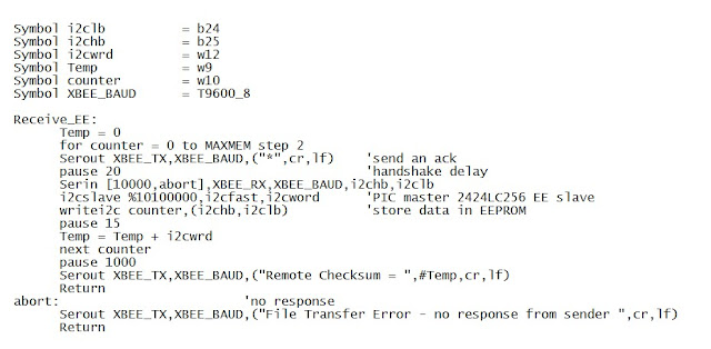
This system works well as
long as there is not a lot of electrical noise in the vicinity and limiting the distance between the remote and base. Testing with other transceivers has not been performed,
but could improve performance. The program was written using the PICAXE
Programming Editor, Version 5.5.1 which supports downloading to slot 4 for the
PICAXE 20X2 chip.
 |
Figure 6
Base Unit Code Transmit Function
|
 |
| Figure 7 Remote Unit Code Receive Function |
