Welcome

Thanks for visiting the Mike's Make blog. It is a compilation of many of my interests. I hope you find the articles in this blog helpful and entertaining. Leave a comment and let me know what you think.

Friday, August 16, 2019

PICAXE OTA Programmer


Making a PICAXE OTA Controller

Michael Shaw, May 2019


In this article I’ll show you how to make a controller using the PICAXE chip that can accept over the air (OTA) program updates. This idea came to me after I mounted the weather station I designed onto the roof of our house.

Figure 1 Weather Station mounted on the peak of our house

What if I discovered a problem with the weather station program and wanted to make changes? What if I wanted to make improvements to the code over time? Do I have to go back up on the roof to reprogram it?

I use PICAXE chips in my projects because they are cheap and easy to use, have a great software platform and are very reliable. There’s just one problem, no one knows how the chip programming (except PICAXE) works. With this system that’s no problem.  We’ll still use the free PICAXE Programming Editor IDE, but updates will be transmitted to the remote unit through the air using a pair of XBEE wireless transceivers, no cables necessary.

The PICAXE system stores programs using what is described as tokenized storage in memory. When you try to print out or decipher a PICAXE program, it’s just gibberish and cannot be understood. Believe me, I’ve tried. But you don’t need to know the meaning behind each of the bytes, just transfer the whole program to the remote unit and reboot the chip!  This system requires the use of two PICAXE controllers, one acting as the base unit and the other as the remote unit. The base unit is used to capture the PICAXE program into an onboard Maxim 24LC256 256K EEPROM memory and then transmits that program verbatim to the remote unit’s onboard 24LC256 EEPROM memory using XBEE wireless transceivers. Then a command is sent to the remote unit to reboot the chip from the remote’s 24LC256 EEPROM onboard memory. 


This system does not work with just any PICAXE chips, however. The chips I use are the PICAXE 20X2 which is a 20 pin PICAXE chip. The reason I use these is because they support the ability to boot the chip from an external EEPROM address using the BOOTI2C command and also supports the #SLOT number software compiler directive which works with the PICAXE Programming Editor Version 5.5.1. So here is a simplified diagram of the system I use to perform OTA program updates to my PICAXE weather station:

Figure 2 Block Diagram of OTA Programming System

Create the PICAXE remote program the way you normally would do using the PICAXE Programming Editor. In the programming directives area place these lines:

#revision 3                        ' increment this for remote updates
'#slot 4                              ' uncomment this when loading into base EEPROM

The first line keeps track of the remote program’s revision number. This is important because when the BOOTI2C command is executed, it looks at the revision number of the program in the 24LC256 EEPROM. If the program revision number is higher than the current program revision number, then it will copy the program from the 24LC256 EEPROM memory into the PICAXE internal memory and reboot the chip.  

The second line is used to direct the program download of the remote program into the base unit’s onboard 24LC256 EEPROM memory. This directive targets the i2c program slot #4 used by X2 parts. When a BOOTI2C 4 command is executed it will copy the contents from the 24LC256 EEPROM memory and load it into internal memory slot 0.

As mentioned earlier, this technique is being used with a solar powered weather station mounted on the roof of the house. The weather station uses the PICAXE chip to collect weather data such as wind speed, outdoor temperature, rain, lightning, light and solar panel and battery status. It transmits this stream of data using an XBEE transceiver to a unit located inside the house once every minute. Because the XBEE transceiver doesn’t need to be on all the time, only when sending the weather data, it is turned off when not in use using a solid state relay. This greatly increases the battery life for this solar powered weather station but presents a problem, though, when you want to send control messages to it. So at the end of every transmitted message, it waits for a few seconds for a command mode message. If it gets the message the XBEE transceiver remains on and commands can be sent to control the weather station or upload a new program.

 After the remote unit is placed in the command mode the upload process begins with the base unit sending the upload command. The remote unit responds by sending an acknowledgment and then waiting for the first 2 bytes from the base unit. After the first bytes are received, the remote again sends and acknowledgement and the process is repeated. If the remote unit fails to receive data from the base unit, it will wait for a specified period of time and then abort the upload. The transfer file size is set to 2000 bytes and the whole file is sent even though the program size (should be) less than that. The reason is there is no way to tell (at least at this moment) where the PICAXE program ends, so a definitive file size is set to insure everything is transferred correctly. To keep it simple, the only error checking is a checksum that the base and remote units calculate. If the checksums match at the end of the transfer then it’s safe to assume that the file was transferred successfully.

Figure 3 PICAXE Terminal showing Successful File Upload

Once the file has been uploaded then a “B” or boot command is sent to the remote which tells the remote unit to execute the BOOTI2C 4 command. This command copies the contents from the 24LC256 EEPROM memory and loads it into the PICAXE internal memory slot 0 and resets the PICAXE, provided that the program revision number is higher than the current program revision number. Otherwise the command will be ignored. 


     Figure 4 Inside the Base Unit

Figure 5 Inside the Weather Station Remote unit


This system works well as long as there is not a lot of electrical noise in the vicinity and  limiting the distance between the remote and base. Testing with other transceivers has not been performed, but could improve performance. The program was written using the PICAXE Programming Editor, Version 5.5.1 which supports downloading to slot 4 for the PICAXE 20X2 chip. 


 Figure 6 Base Unit Code Transmit Function

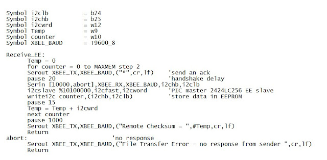
Figure 7 Remote Unit Code Receive Function


Sunday, June 17, 2018

Making The Pill Bottle Radio


Making of The Pill Bottle Radio


Michael Shaw, June 2018


Pill Bottle Radio


If you’re like me, you like to have a portable AM/FM radio on hand just in case you want to catch your favorite shows or to hear the news. Now this being hurricane season, it’s also great to have for emergencies too! In this article I’ll explain how to make a good quality rechargeable portable radio that fits inside a recycled pill bottle. It’s pretty easy and cost less than $50 and takes only a few hours to make, if you don’t count the time it takes to make the 3D printed cap.

This design was inspired after realizing I didn’t have a good enclosure to mount the components of the radio I just built in. I had purchased a SparkFun ESP8266 Thing WIFI Internet Board and interfaced it to the SparkFun FM Tuner Evaluation Board and a Lithium Ion battery.


SparkFun ESP8266 Thing
SparkFun FM Tuner Evaluation Board


I looked at other implementations on the internet and really didn’t want to wire up switches or controls to use the radio. Instead, I used the AP WEB server WIFI capabilities of the SparkFun ESP8266 Thing to implement the controls on a web page.

Since I’m older I now have to take maintenance drugs on a daily basis. This means I have a few empty prescription bottles lying around. I happened to take the components of the FM radio and slip them into an empty pill bottle and realized it all fit! I just needed to figure out how to mount it all in the pill bottle so I could plug in the head phones and the charger. I thought about cutting slots and poking holes in the existing cap but this wasn’t the best solution. What I needed to do was to make my own cap so it would be strong and work reliably. At about this time I got my first 3D printer, so I set out to make my own cap with the supports and mounting holes that I needed.

I used a free 3D CAD program to come up with the following drawing for a new pill bottle cap with the mounting for the boards built in:


I had to make a few iterations until I got the cap just right, since it was trial and error to get the threads correct. By the way, the pill bottle size is known as a 30 DRAM size bottle and is approximately 38mm in diameter at the center.

Once the cap was finished it was just a matter of wiring up the ESP8266 Thing to the FM Tuner Evaluation Board. I wired the boards together using the wiring diagram below:


Now I was ready to program the ESP8266 Thing with some software. The software I created is basically a mash-up of the SparkFun’s ESP8266 AP Web Server example sketch and the Si4703_breakout test sketch. Note: to fit both the boards in the bottle you can’t use any headers to connect the two boards together, except for the DTR/RST jumper. Instead I direct wired both boards together as you can see in the picture below:


This is a problem, though, because you won’t be able to connect the programmer. You can make a short wiring harness by soldering wires to header pins and then tucking them out of the way or you can use pogo pins (what I used) to temporarily  connect the FTDI communications interface to the ESP8266 Thing.

Once programmed you’re ready to try it out. Plug in the battery to the Thing and turn it on. Connect to WIFI on your phone and look for the WIFI network named “Radio Thing nnnn”, where nnnn is the last digits of the Thing’s MAC address. Connect to the network and when prompted, enter the password “Sparkfun”. Now open the browser on your phone and enter the address 192.168.4.1/ and the screen similar to the following should be displayed:


Now you can type in “up” or “down” after the network address to change the volume or type the letters a,b,c to switch to a pre-programmed station. These are my settings, but you can change them in the Thing’s program to whatever you want.

I’m really happy with the performance and the sound quality of the radio and not having to wire a bunch of switches and knobs to get it working is icing on the cake.  Plus I have a sturdy enclosure that was cheap and easy to make, if you have a 3D printer.  The files you need to make on just like it will be listed here. Thanks and enjoy some easy listening!  

Tuesday, January 12, 2016

Using the Jameco Kitpro CJKIT-20808 with a Bescor Motorized Pan & Tilt Head


The Jameco Kitpro CJKIT-20808 Surveillance Camera Pan & Tilt Decoder Kit Assembled found on EBay allows you to interface a surveillance camera system Pan and Tilt capability to the outside world. 


An example of this is using the Jameco CJKIT-20808 board to interface to a Bescor Motorized Pan & Tilt Head with Power supply and Extension Cord Kit

Bescor Motorized Pan & Tilt Head


The Bescor Motorized Pan & Tilt Head is a very capable Pan & Tilt device and according to the description can support payloads up to 6 lbs. It has a Remote Socket that is used with a remote control, but for our purposes we will use it to interface it with a surveillance camera system.

Note: although it’s pretty safe to control the Bescor Motorized Pan & Tilt Head using the method described in this blog, this blogger still accepts no responsibility for damage to your equipment.

Wiring the Pan-Tilt-Zoom (PTZ) decoder to the Bescor Motorized Pan & Tilt Head is easy, all you need is a 7 pin DIN connector and some wire and cable. Here is a picture of the wiring I did connecting the Bescor to the Jameco CJKIT-20808 PTZ Decoder board (note: the white wires are jumpers connecting the commons together.) 


The diagram below shows how to connect the wiring to the PTZ decoder and Remote Socket connector. The white common wire is replaced by the purple colored wire in the diagram below:  


The red jumper is for the speed control. Jumping these two connections gives the max speed control. That’s it! Plug the connector into the Remote Socket of the Bescor Motorized Pan & Tilt Head and place the mode switch into the “M” or manual position and turn it on.
Connect the wires from the RS485 connector on the Jameco CJKIT-20808 PTZ Decoder board to your surveillance camera system and make sure the address, protocol and baud rates of the two devices match. Now you can now control the motion of the Bescor Motorized Pan & Tilt from the Pan and Tilt controls of your surveillance camera system. 

Wednesday, June 5, 2013

Mounting Design for Harbor Freight Solar Panels

  Mounting Design for Harbor Freight Solar Panels
by Michael Shaw, May 2013

Harbor Freight sells an economical solar energy kit that I bought several years ago for less than $200. This kit is advertised as a 45 watt DC system that contains three solar panels, a charge controller/DC supply unit, two 12VDC lamps and all the wiring needed. The only thing you need to supply is a 12VDC car battery. For several years I used it as an auxiliary power source after several hurricanes struck south Florida in 2005 (see my June 2012 blog post “Notes on Surviving a Hurricane”). But what I really wanted to do is get more use from them, so I decided I would use the system to create power for a remote utility shed in the back yard. It could be used for interior or exterior lights, or to power an outdoor fountain or even for 12VDC ventilation fans inside the shed. The only problem was the mounting brackets that came with the kit were really only meant for temporary use and not for a permanent setup. What I needed was an inexpensive and secure way to mount the three panels on the roof of a corrugated aluminum roof shed. 

I decided to make my own mounts after searching the web for affordable PV mounting brackets. Most of the mounting hardware I found on the web was for mounting standard PV panels with higher wattages and dimensions of around 39”X64”. What I wanted didn’t exist, so I decided to make my own. What I needed was a design that was light-weight, wouldn’t rust and could be mounted on a corrugated shed roof, and, oh yeah, cheap. After wandering the local Home Depot store I came across some aluminum metal stock that would do the trick.

What my wife and most females don’t understand about men is that when we walk the isles of a store, in particular a hardware store, our minds are in “tool acquisition” mode. What we are doing in this mode is looking at everything available in the store and deciding if it is A) something that looks cool, B) could it be useful as a weapon or a tool and C) can be turned into something that could be useful as a weapon or a tool. That is why it can take us hours to pick up “some screws” at the local hardware store. So now you know, deal with it.

The aluminum C channel stock I bought would be used as the rails to mount the panels on and the square stock I bought would be used as mounting brackets and act as spacers between the corrugated sections of the roof. I put it all together using stainless steel nuts, washers and screws. The following drawings show how it all came together:


A 96” length of “C” channel stock was cut to span the length of the 3 panels with about .25” between the panels for the ¼ X 20 screws.  I cut 4 pieces of the ¾” X 1/16” square tubing at about 0.89” in length for the end stand-offs, and 4 more pieces about 1” in length for the mounting brackets.  Then I used 4 1/4X3” lag screws and washers to secure the rails to the roof of the shed as in the picture below.


I mounted the rails so they were conveniently located over the center of the roof support beams (this is identified by the location of the roofing screws securing the roofing panels). Then I caulked the bottom of the mounting brackets and used aluminum tape around the bottom of the mounting bracket to act as flashing to keep the mounts from leaking when it rains.
With the rails mounted it was time to install the panels. It’s easier to put the ¼ X20 screws between the panels in before installing the panels, that way all you have to do is slide the panel under the screw. It’s hard to screw the nut, lock washer and flat washer onto the end of the screw after the panels are in place.  

Once the panels were in place, I ran the individual wires from the panels to the junction box where I connected them in parallel using a terminal strip I bought at Radio Shack and mounted inside the junction box.


Then I ran a cable from the junction box up under the roof and down to the controller inside the shed.
   

In the completed mounting design, as a safety measure I attached a bare copper wire to the solar panel mounting rails and to a grounding rod driven 6’ into the ground at the corner of the shed (not shown). This protects the system from the possibility of lightning.


The system has only been in place for about a month, but it should last for many years to come.

Saturday, February 16, 2013


I have done many improvements to PTZ decoder design 
described in my previous posts and you can now get it as a kit 


Wednesday, July 11, 2012

Making a Camera PTZ Decoder


Making a Camera PTZ Decoder

by Michael Shaw, July 2012

 This article explains the design of a Pan-Tilt-Zoom (PTZ) decoder that is used with a camera surveillance system. These systems are used for remotely positioning surveillance cameras and uses twisted pair RS485 for the physical connection. I made this decoder for use with a Maxwell MP-101 electronic power panner, and since this unit only has pan and tilt capability, this article is really about making a pan/ tilt decoder.

PTZ Decoder Interfaced with the Maxwell MP-101 Power Panner
The serial communications format that’s used to talk to the PTZ decoder has been standardized over the years, with the most popular format being the Pelco “D” protocol. I got the specifics of the Pelco D protocol from the website at CommFront,  http://www.commfront.com/RS232_Examples/CCTV/Pelco_D_Pelco_P_Examples_Tutorial.HTM. The picture in figure1 shows a DVR 4 camera system with the PTZ control in the bottom right panel. The DVR system controls a particular PTZ positioning device using a specific address for each decoder. Up to 255 different addresses can be assigned.   

Figure 1, example of a DVR Pan Tilt control panel


The Pelco “D” serial protocol will work with baud rates from 300 baud  up to 9600 baud. The protocol consists of a 7 byte control message that contains the information needed for controlling a PTZ device. The information in this control message contains the address of the device being controlled and the direction and speed of motion. The format of the command is as follows: (note: all values in hex)


Byte 1
Byte 2
Byte 3
Byte 4
Byte 5
Byte 6
Byte 7
Sync
Camera Address
Command 1
Command 2
Data 1
Data 2
Checksum


Byte 1 (sync), the synchronization byte, fixed at FF
Byte 2 (Camera Address), defined range is between 1-FF

Byte 3 (Command 1), first set of control parameters (explained below)

Byte 4 (Command 2), second set of control parameters (explained below)

Byte 5 (Data 1), pan speed parameters ranging from 00 (stop) to 3F (high speed) and FF for turbo (maximum speed of device)

Byte 6 (Data 2), tilt speed parameters ranging from 00 (stop) to 3F (maximum)

Byte 7 (Checksum), sum of bytes (excluding sync byte) then modulo 100
Bytes 3 and 4 are used for the Command 1 and Command 2 control information and are encoded in the following format:

Bit 7
Bit 6
Bit 5
Bit 4
Bit 3
Bit 2
Bit 1
Bit 0
Command 1
Sense
Reserved
Reserved
Auto/Manual Scan
Camera On/Off
Iris Close
Iris Open
Focus Near
Command 2
Focus Far
Zoom Wide
Zoom Tele
Tilt Down
Tilt Up
Pan Left
Pan Right
Fixed to 0

The Maxwell MP-101 electronic power panner has a connector that is used by a remote control to control the position of the camera. This connector will be used for interfacing the decoder to the Maxwell power panner. All the Maxwell power panner needs is a contact closure to activate the desired pan or tilt motion. The decoder uses relays to provide this contact closure, so all that’s needed is to detect the Tilt up/down and Pan left/right commands in the Pelco D message.
I used a PICAXE 18M2 chip as the controller in this decoder design. The PICAXE 18M2 chip is real easy to work with and provides enough I/O pins to do what I want to do. I’ll need 4 outputs for the relays that will be controlling the direction of motion; these are tilt up, tilt down, pan left and pan right. I also want to be able to provide a way for assigning an address to the decoder, so I’ll need 8 pins for that.  To make it easy, I’ve fixed the baud rate at 4800, but I’ll need a pin for the serial input coming from the RS485 transceiver chip and an output pin for a status LED. The schematic for the decoder is pictured in figure 2.

Figure 2, PTZ Decoder Schematic
The software for the decoder is pretty straight forward. When it first starts, it reads the unit address switches then waits for a serial message to arrive. When a serial message is received, it verifies that the checksum is correct and then checks the unit address for a match. If the addresses match then it checks for the pan and tilt commands in the command 2 message.
The software checks for a total of 8 conditions for the pan tilt operations since pan and tilt control could be combined in a single message. The following is a truth table and the resulting values for the various pan/tilt conditions:
Command 2
Tilt Down
Bit 4
Tilt Up
 Bit 3
Pan Left
Bit 2
Pan Right
Bit 1
Fixed to 0
Bit 0

16
8
4
2
1
2


X

4


X


8

X


16
X


10

X

X

18
X


X

12

X
X


20
X

X


The design prototype was constructed in about a day on a PC board from Radio Shack. The components were purchased from several different suppliers. The average cost to build the decoder was around $50.

Picture of the PTZ Decoder Prototype


The Decoder Parts List

Ref
Quantity
Description
Part Number
Vendor
RLY1-RLY4
4
SPDT 5V Relay
275-0240
RadioShack
PCB1
1
Prototype PC Board
276-168
RadioShack
U2
1
RS485 transceiver, 5V, 8pin DIP
LTC485CN8#PBF-ND
Digi-Key
U3
1
5V voltage regulator
COM-00107
SparkFun
U1
1
PICAXE 18M2 Microcontroller
COM-10187
SparkFun
SOCKET1
1
18 pin DIP Socket
PRT-07940
SparkFun
SOCKET2
1
8 pin DIP Socket
PRT-07937
SparkFun
J1
1
DC Power Jack
PRT-00119
SparkFun
J2
1
2-pin PCB mount Spring Terminal
PRT-08073
SparkFun
C2
1
Capacitor, 100uf, 50VDC
272-1044
RadioShack
C3
1
Capacitor, 10uf, 10VDC
55047371
RadioShack
C1,C4
2
Capacitor, .1uf, 50VDC
399-4266-ND
Digi-Key
R5
1
330 ohm 0.25W resistor
271-1315
RadioShack
D5
1
Green LED
COM-09592
SparkFun
RN1
1
10K ohm, 9 resistor network
CSC10KY-ND
Digi-Key
R1-R4
4
10K ohm, 0.25W resistors
271-1335
RadioShack
SW1-SW8
1
8 position DIP switch
COM-08034
SparkFun
Q1-Q4
4
2N3904 NPN Small Signal Transistors
COM-00521
SparkFun
D1-D4
4
1N4005 Diodes
276-1104
RadioShack
PWR1
1
Wall Adapter Power Supply, 9VDC
TOL-00298
SparkFun
AR
24 AWG hookup Wire


This decoder design works as expected with a typical DVR setup and is relatively inexpensive to make. You no longer have to be satisfied with a single camera view and can position the camera remotely to view the area of interest. In the next design I will incorporate PWM controlled motors into the circuit, and eliminate the relays. This will allow me to create a complete PTZ unit.

Below is a copy of the PICAXE code
 'PTZ Decoder FOR PICAXE 18M2
 'decodes Pelco "D" type signals
 'By Mike Shaw 7/2012
 'Settings Baud 4800,8,N,1
 Symbol LED    = C.2
Symbol Relay1 = C.6     ' Tilt Up
Symbol Relay2 = C.7     ' Tilt Down
Symbol Relay3 = C.0     ' Pan Right
Symbol Relay4 = C.1     ' Pan Left
Symbol stx   =      b0
Symbol adr   =     b1
Symbol cmd1  =   b2
Symbol cmd2  =   b3
Symbol dat1  =     b4
Symbol dat2  =     b5
Symbol chks  =     b6
Symbol my_adr = b7
Symbol tmp   =     b8

Symbol RX_PIN = C.5                 'Input from RS485 chip
Symbol RX_BAUD = T4800       'Baud fixed at true 4800
Gosub GetADD
Do
 Gosub GetPacket
 If adr = my_adr Then
 Gosub HandlePacket
 End If
 Loop
 GetPacket:
 Do
 SerIn RX_PIN,RX_BAUD,stx,adr,cmd1,cmd2,dat1,dat2,chks
 tmp = adr + cmd1 + cmd2 + dat1 + dat2
 Loop Until tmp = chks
 Return

 GetADD:  ' Read then Display Unit Address
 my_adr = pinsB ^ 001111     'invert address
 for b0 = 1 to my_adr
 high LED
 pause 300 
 low LED
 pause 300
 next b0
 high LED
 Return

 HandlePacket:
 low LED
 if cmd2 = 2 then high Relay3 End If     'Pan Right
 if cmd2 = 4 then high Relay4 End If     'Pan Left
 if cmd2 = 8 then high Relay1 End If      'Tilt Up
 if cmd2 = 10 then high Relay3 End If    'Relay1 Pan Right & Tilt Up
 if cmd2 = 12 then high Relay4 End If    'Relay1 Pan Left & Tilt Up
 if cmd2 = 16 then high Relay2 End If'   'Tilt Down
 if cmd2 = 18 then high Relay3 End If    'Relay2 Pan Right & Tilt Down
 if cmd2 = 20 then high Relay4 End If    'Relay2 Pan Left & Tilt Down
 pause 1000   ' 1 sec delay
 low Relay1,Relay2,Relay3,Relay4
 high LED
 Return